- Home
- Technology
Technology
Technology

Background of Invention
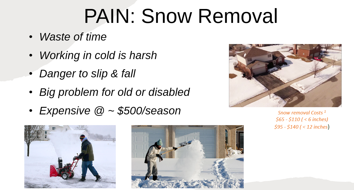
Snow removal from sidewalks, driveways, parking lots, roads and other such places is a waste of time, tiring, inconvenient, with a danger of slipping and falling or having a heart attack for many old and fragile people. Many people hire expensive annual snow removal services to avoid having to clear the snow themselves.
Autonomous machines that are in the market tend to be fully electric and are expensive. Many of them also involve installation of special equipment on the property, such as underground wires or multiple poles with sensors that provide an onboard sensor with its location on the property.
Machines which rely on battery power have limited range. They are ok for small property lots but will need frequent battery changes for bigger lots. This can be a huge inconvenience to the user.
Developing a new snowblower design is also a large undertaking that takes a lot of time and resources. In this invention, a method and architecture are designed to take an existing manual snowblower design and make it autonomous.
The concept can further be extended to farming equipment – which tends to be gas driven – as they are power hungry huge machines. Here also electric motors can be used only to steer and control the various attachments that are used in the application.
One could also see this concept extended to road making bulldozers, street cleaning machines and other power-hungry applications.

Patent Abstract
This invention relates to an autonomous snow removal machine for residential use. The machine is created by converting a manually operated snowblower to electric operation using motors, sensors, and a small computer. Key functions like wheel movement, chute control, and auger engagement are now powered by electric motors, while the auger rotation remains driven by the original gas engine or electric motor. Onboard sensors provide data to the control computer, enabling autonomous snow clearing within a defined area. The user interacts with the machine through a smartphone application to define the clearing zone and initiate the autonomous process.The machine can be operated manually when required by disengaging the clutch mechanism at the wheels and other electric motors.

Drawings and Explanation
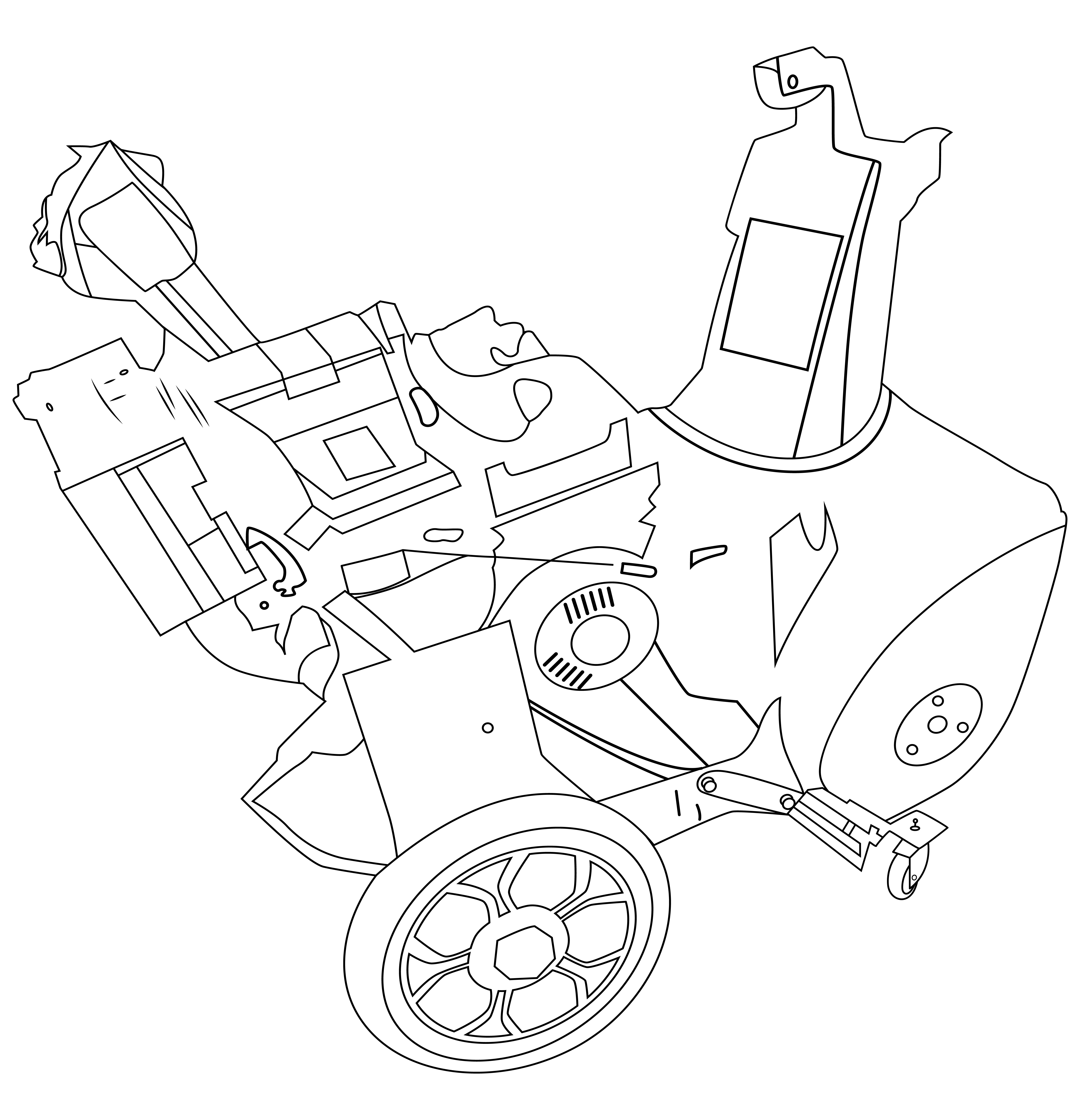
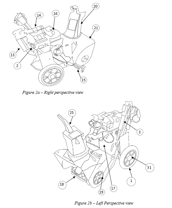
Explanation of labels used in the drawing 2:
- Electric drive chute control (DC motor with worm gear shaft)
- Edge compute module
- Electric linear actuator for engaging the auger rotation.
- Sensor 1 – front camera
- Sensor 2 – rear camera
- Sensor 3 – ultrasonic – front (optional)
- Sensor 4 – ultrasonic – rear (optional)
- Sensor 6 – GPS sensor (optional)
- Sensor 7 – IMU (inertial Measurement unit, Optional)
- Sensor 8 – wheel speed sensor (optional)
- Optional sensors (lidar)
- Optional sensor (radar)
- Battery for wheels
- Battery for chute, deflector and Auger rotation engagement control
- Front swivel wheels
- Gas engine to rotate auger
- electric start button for gas engine
- auger to pull the snow into the chute
- Belt drive mechanism to rotate the auger from the gas engine
- chute for directing the snow out when pushed in by rotating auger
- Snow bucket that encloses the auger
- Smartphone Application for interfacing with the autonomous snowblower
